8 Year Exporter Die Forging Process - Forged Shaft – DHDZ
8 Year Exporter Die Forging Process - Forged Shaft – DHDZ Detail:
Open Die Forgings Manufacturer In China
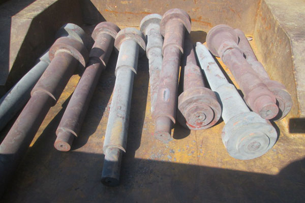
FORGED SHAFT / STEP SHAFT/ SPINDLE / AXLE SHAFT
The application fields of forgings shaft are
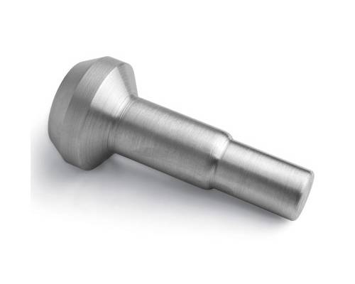
Shaft forgings (mechanical components) Shaft forgings are cylindrical objects that are worn in the middle of the bearing or in the middle of the wheel or in the middle of the gear, but a few are square. A shaft is a mechanical part that supports a rotating part and rotates therewith to transmit motion, torque or bending moments. Generally, it is a metal rod shape, and each segment can have a different diameter. The parts of the machine that make the slewing movement are mounted on the shaft. Chinese name shaft forging type shaft, mandrel, drive shaft material use 1, carbon steel 35, 45, 50 and other high-quality carbon structural steel because of its high comprehensive mechanical properties, more applications, of which 45 steel is used most widely. In order to improve its mechanical properties, normalizing or quenching and tempering should be carried out. For structural shafts that are not important or have low forces, carbon structural steels such as Q235 and Q275 can be used. 2, alloy steel Alloy steel has higher mechanical properties, but the price is more expensive, mostly used for shafts with special requirements. For example, high-speed shafts using sliding bearings, commonly used low-carbon alloy structural steels such as 20Cr and 20CrMnTi, can improve the wear resistance of the journal after carburizing and quenching; the rotor shaft of the turbo generator works under high temperature, high speed and heavy load conditions. With good high temperature mechanical properties, alloy structural steels such as 40CrNi and 38CrMoAlA are often used. The blank of the shaft is preferred for forgings, followed by round steel; for larger or complex structures, cast steel or ductile iron can be considered. For example, the manufacture of a crankshaft and a camshaft from ductile iron has the advantages of low cost, good vibration absorption, low sensitivity to stress concentration, and good strength. The mechanical model of the shaft is the beam, which is mostly rotated, so its stress is usually a symmetric cycle. Possible failure modes include fatigue fracture, overload fracture, and excessive elastic deformation. Some parts with hubs are usually installed on the shaft, so most shafts should be made into stepped shafts with a large amount of machining. Structural Classification Structural Design The structural design of the shaft is an important step in determining the reasonable shape and overall structural dimensions of the shaft. It consists of the type, size and position of the part mounted on the shaft, the way the part is fixed, the nature, direction, size and distribution of the load, the type and size of the bearing, the blank of the shaft, the manufacturing and assembly process, the installation and transport, the shaft The deformation and other factors are related. The designer can design according to the specific requirements of the shaft. If necessary, several schemes can be compared to select the best design.
The following are the general shaft structure design principles
1. Save materials, reduce weight, and use equal-strength shape. Dimensional or large section coefficient cross-sectional shape.
2, easy to accurately position, stabilize, assemble, disassemble and adjust the parts on the shaft.
3. Use various structural measures to reduce stress concentration and improve strength.
4. Easy to manufacture and ensure accuracy.
Classification of shafts Common shafts can be divided into crankshafts, straight shafts, flexible shafts, solid shafts, hollow shafts, rigid shafts, and flexible shafts (flexible shafts) depending on the structural shape of the shaft.
The straight shaft can be further divided into
1 shaft, which is subjected to both bending moment and torque, and is the most common shaft in machinery, such as shafts in various speed reducers.
2 mandrel, used to support the rotating parts only to bear the bending moment without transmitting torque, some mandrel rotation, such as the axle of the railway vehicle, etc., some of the mandrel does not rotate, such as the shaft supporting the pulley.
3 Transmission shaft, mainly used to transmit torque without bending moment, such as long optical axis in crane moving mechanism, drive shaft of automobile, etc.
The material of the shaft is mainly carbon steel or alloy steel, and ductile iron or alloy cast iron can also be used. The working capacity of the shaft generally depends on the strength and stiffness, and the high speed depends on the vibration stability. Application Application Torsional stiffness The torsional stiffness of the shaft is calculated as the amount of torsional deformation of the shaft during operation, measured in terms of the torsion angle per meter of shaft length. The torsional deformation of the shaft should affect the performance and working accuracy of the machine. For example, if the torsion angle of the camshaft of the internal combustion engine is too large, it will affect the correct opening and closing time of the valve; the torsion angle of the transmission shaft of the gantry crane motion mechanism will affect the synchronism of the driving wheel; A large torsional stiffness is required for shafts that are at risk of torsional vibration and shafts in the operating system.
Technical requirements 1. Machining accuracy
1) Dimensional accuracy The dimensional accuracy of shaft parts mainly refers to the diameter and dimensional accuracy of the shaft and the dimensional accuracy of the shaft length. According to the requirements of use, the accuracy of the main journal diameter is usually IT6-IT9, and the precision journal is also up to IT5. The shaft length is usually specified as the nominal size. For each step length of the stepped shaft, the tolerance can be given according to the requirements of use.
2) Geometric accuracy Shaft parts are generally supported on the bearing by two journals. These two journals are called support journals and are also the assembly reference for the shaft. In addition to the dimensional accuracy, the geometric accuracy (roundness, cylindricity) of the supporting journal is generally required. For journals of general accuracy, the geometry error should be limited to the diameter tolerance. When the requirements are high, the tolerance values allowed should be specified on the part drawing.
3) Mutual positional accuracy The coaxiality between the mating journals (the journals of the assembled drive members) in the shaft parts relative to the support journals is a common requirement for their mutual positional accuracy. Generally, the shaft with normal precision, the matching precision with respect to the radial runout of the support journal is generally 0.01-0.03 mm, and the high-precision shaft is 0.001-0.005 mm. In addition, the mutual positional accuracy is also the coaxiality of the inner and outer cylindrical surfaces, the perpendicularity of the axially positioned end faces and the axial line, and the like. 2, surface roughness According to the precision of the machine, the speed of the operation, the surface roughness requirements of the shaft parts are also different. In general, the surface roughness Ra of the supporting journal is 0.63-0.16 μm; the surface roughness Ra of the matching journal is 2.5-0.63 μ m.
The processing technology 1, the selection of the material shaft parts of the shaft parts, Mainly based on the strength, stiffness, wear resistance and manufacturing process of the shaft, and strive for economy.
Common used material: 1045 | 4130 | 4140 | 4340 | 5120 | 8620 | 42CrMo4 | 1.7225 | 34CrAlNi7 | S355J2 | 30NiCrMo12 |22NiCrMoV |EN 1.4201 |42CrMo4
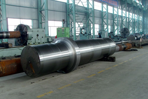
FORGED SHAFT
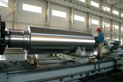
Large forged Shaft up to 30 T.. Forging ring tolerance typically -0/+3mm up to +10mm dependent on size.
●All Metals has the forging capabilities to produce forged ring from the following alloy types:
●Alloy steel
●Carbon steel
●Stainless steel
FORGED SHAFT CAPABILITIES
Material
MAX DIAMETER
MAX WEIGHT
Carbon, Alloy Steel
1000mm
20000 kgs
Stainless Steel
800mm
15000 kgs
Shanxi DongHuang Wind Power Flange Manufacturing Co., LTD., as an ISO registered certified forging manufacturer, guarantee that the forgings and/or bars are homogenous in quality and free of anomalies which are detrimental to the mechanical properties or machining properies of the material .
Case:
Steel Grade BS EN 42CrMo4
BS EN 42CrMo4 Alloy Steel Relevant Specifications and Equivalents
|
42CrMo4/1.7225 |
C |
Mn |
Si |
P |
S |
Cr |
Mo |
|
0.38-0.45 |
0.60-0.90 |
0.40 max |
0.035 max |
0.035 max |
0.90-1.20 |
0.15-0.30 |
| BS EN 10250 | Material No. | DIN | ASTM A29 | JIS G4105 | BS 970-3-1991 | BS 970-1955 | AS 1444 | AFNOR | GB |
| 42CrMo4 | 1.7225 | 38HM | 4140 | SCM440 | 708M40 | EN19A | 4140 | 42CD4 | 42CrMo |
The steel grade 42CrMo4
Applications
Some typical application areas for EN 1.4021
Pump- and Valve parts, Shafting, Spindels ,Piston rods, Fittings, Stirrers,Bolts,Nuts
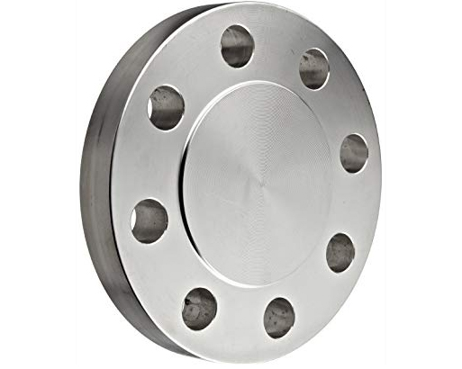
EN 1.4021 Forged ring , Stainless Steel forgings for Slewing ring
Size: φ840 x L4050mm
Forging (Hot Work ) Practice , Heat Treatment Procedure
|
Forging |
1093-1205℃ |
|
Annealing |
778-843℃ furnace cool |
|
Tempering |
399-649℃ |
|
Normalizing |
871-898℃ air cool |
|
Austenize |
815-843℃ water quench |
|
Stress Relieve |
552-663℃ |
|
Quenching |
552-663℃ |
DIN 42CrMo4 Alloy Steel Mechanical Properties
|
Size Ø mm |
Yield stress |
Ultimate tensile Stress, |
Elongation |
Hardness HB |
Toughness |
|
Rp0.2,N/nn2, min. |
Rm,N/nn2 |
A5,%, min. |
KV, Joule, min. |
||
|
<40 |
750 |
1000-1200 |
11 |
295-355 |
35 at 20ºC |
|
40-95 |
650 |
900-1100 |
12 |
265-325 |
35 at 20ºC |
|
>95 |
550 |
800-950 |
13 |
235-295 |
35 at 20ºC |
|
Rm - Tensile strength (MPa) (Q +T) |
≥635 |
|
Rp0.2 0.2% proof strength (MPa) (Q +T) |
≥440 |
|
KV - Impact energy (J) (Q +T) |
+20° |
|
A - Min. elongation at fracture (%)(Q +T) |
≥20 |
|
Z - Reduction in cross section on fracture (%)(N+Q +T) |
≥50 |
|
Brinell hardness (HBW): (Q +T) |
≤192HB |
ADDITIONAL INFORMATION
REQUEST A QUOTE TODAY
OR CALL: 86-21-52859349
Product detail pictures:


Related Product Guide:
To get the stage of realizing dreams of our employees! To build a happier, more united and much more skilled crew! To reach a mutual benefit of our prospects, suppliers, the society and ourselves for 8 Year Exporter Die Forging Process - Forged Shaft – DHDZ , The product will supply to all over the world, such as: Kenya, Niger, Finland, As a way to use the resource on the expanding info in international trade, we welcome prospects from everywhere on the web and offline. In spite on the high quality items we offer, effective and satisfying consultation service is supplied by our qualified after-sale service group. Item lists and detailed parameters and any other info weil be sent to you timely for the inquiries. So please make contact with us by sending us emails or call us when you've got any questions about our organization. ou could also get our address information from our site and come to our enterprise. We get a field survey of our merchandise. We are confident that we'll share mutual accomplishment and create solid co-operation relations with our companions within this market place. We're seeking forward for your inquiries.
We have been appreciated the Chinese manufacturing, this time also did not let us disappoint,good job!

